QuirkyPolyline: exposing foolish programmers

In AutoCAD, the AcDbCurve class defines a general parametrized curve. On a parametrized curve, points in space are mapped to real numbers (parameters) by an arbitrary function F(p) for values of p from the curve start parameter to the curve end parameter. Defining a curve this way simplifies working with complex 3D curves because one can work in the curve’s one dimensional “parameter space” instead of the more complex three dimensional cartesian space.

The choice for how to parametrize a curve entity is up to the implementor. Parameters are designed to be opaque, so consumers of parametrized curves must make no assumptions about how a specific curve implements them. The only thing guaranteed about the parameters of a curve is that all points on the curve map to a unique parameter in a continuous range from the starting parameter to the ending parameter.

AutoCAD entities such as lines, circles, arcs, polylines, rays, and others are derived from AcDbCurve. These basic curve entities have very simple and straighforward parameter mappings that can be reverse engineered with very little effort, so lazy programmers sometimes make assumptions that are not guaranteed to always be true. Even smart programmers often get tripped up on parametrized curves because they use parameter space when they should be using distance space (that is, distance along the curve). The AcDbCurve interface provides functions to translate from parameter space back and forth to distance space, as well as back and forth to three dimensional cartesian space.

Wise programmers always let the curve itself perform all translations to or from distance space or cartesian space so that their code never relies on the actual value of a parameter. Foolish programmers take shortcuts by making assumptions about parameter values. For example, it happens that in all past versions of AutoCAD, the parameter of the midpoint of a polyline segment is exactly halfway between the segment starting parameter and the segment ending parameter, and the segment starting and ending parameters are always equal to the index number of the corresponding vertex. A foolish programmer (e.g. here and here) may use this knowledge to calculate the midpoint of the segment by guessing it’s parameter. The foolish programmer’s code will fail when a case arises where that guess is wrong. It is the purpose of QuirkyPolyline to provide such a case.

QuirkyPolyline defines a QPOLY command that prompts for a selection set of lightweight polylines in AutoCAD, then converts the selected polylines to “quirky polylines” that expose a completely different parameter scheme. Quirky polylines look and act perfectly normal in all respects. If you save quirky polylines, they will be stripped of their quirkiness. There are no long term effects of making polylines quirky; it’s just a temporary change that wears off on its own.

Making quirky polylines is useful for testing code that works with parametrized curves. If your code makes assumptions that it shouldn’t, quirky polylines will expose the error of your ways. Over the years, I have had arguments with people who insisted that their assumption had been validated by extensive testing. My counterargument is that someone, somewhere (possibly even Autodesk itself) already has or eventually will generate a derived entity where the assumption is not true. In addition to providing a proving ground, QuirkyPolyline is designed to demonstrate to the naysayers that unusual parametrization implementations can exist in the wild.

The download contains ARX modules for AutoCAD 2000 through AutoCAD 2015. To use QuirkyPolyline, just load the module that matches your version and architecture of AutoCAD. Create a lightweight polyline with the PLINE command, then use the QPOLY command to convert the normal polyline to a quirky polyline. You can use the LIST command to verify that it did become quirky, but you should notice no other detectable changes.

[Note: the download has since been updated and moved to the ARX freebies page]

Here is a useful little lisp function that defines a PP command for displaying the parameter value of a picked point on a selected curve entity. You can use this to explore other curve entities, and to see how the polyline’s parametrization changes after it becomes quirky.


(vl-load-com)
(defun C:PP (/ sel pointoncurve param)
(if (setq sel (entsel))
(progn
(setq pointoncurve (apply 'vlax-curve-getclosestpointto sel))
(setq param (vlax-curve-getparamatpoint (car sel) pointoncurve))
(princ (strcat "nParam = " (rtos param)))
)
)
(princ)
)

I hope this helps you avoid the pitfalls of parametric curve code. Remember, don’t be a foolish programmer!
Automatic LISP Loading

There are a myriad of ways to load AutoLISP applications in AutoCAD, including acaddoc.lsp, an .mnl file, the Startup Suite, and manually by various means. For application developers wishing to deploy their applications to others, all of these methods have drawbacks. The ideal solution should be easy to implement in an installation program, require minimal or zero changes to the user’s AutoCAD configuration, work the same way across all versions of AutoCAD, and easily undone when the application is uninstalled.

ObjectARX application developers have long used registry demand loading to load their applications automatically, either when AutoCAD starts or when the user enters a command that the application defines. Registry demand loading is relatively easy to set up and meets the other requirements for an ideal solution, except for one problem: it works only with ObjectARX modules (or with .NET modules in AutoCAD 2006 and later).

Many years ago, I created a solution to this problem by building a small stub ObjectARX module that did nothing but load an associated LISP file. This effectively allows the registry demand loading mechanism to be used for loading a LISP file. If you develop AutoLISP applications that could benefit from registry demand loading, then I have a Christmas present for you: LspLoad.zip contains a complete suite of newly updated stub modules for all versions of AutoCAD from AutoCAD 2000 to AutoCAD 2010, plus modules for Bricscad 9 and 10, which also supports registry demand loading.

To use the stub modules, just rename them so that the base filename matches your application’s main LISP filename, then install them in the same folder as the LISP file and create the registry demand load entries. The only work you have to do is to get the stub module to load. You can simply drag and drop the appropriate stub module into a running instance of AutoCAD in order to test it.

[Update 2014-02-18: See Building a commercial grade lisp plugin installer in 5 easy steps for a solution to setting up the demand load keys using Inno Setup.]

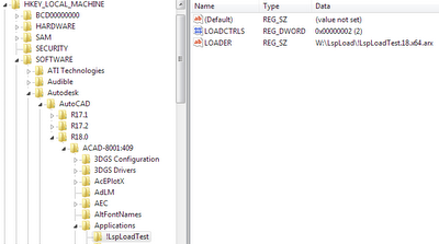
Creating the demand loading registry keys is not difficult, but it may require some programming. I write custom actions for my installation programs that enumerate all installed AutoCAD versions and flavors, and set up the demand load keys for every one. However you do it, the final result should look something like this (for AutoCAD 2010 on my system):

In this screen shot, I created an application called “!LspLoadTest” (the “!” was added just so it displayed at the beginning of the list). I added the minimum required subkeys. The LOADER string value is set to the complete path of the stub module, and LOADCTRLS is set to a value of 2, which means I want the application loaded when AutoCAD starts. LOADCTRLS is a bit coded value; for use with LspLoad, it’s only useful values are 2 or 4. A value of 4 means “load when my command is invoked”; this mode requires a COMMANDS subkey that lists the defined commands.

The way it works is very simple. In the example above, you can see that I renamed the module (but left the “.18.x64.arx” so that I can tell it apart). I then added !LspLoadTest.lsp to the W:LspLoad folder. That file contained the following:

(princ “nThis test file loaded from “)
(princ (if GetPathOf!LspLoadTest (GetPathOf!LspLoadTest) “<unknown>”))
(princ)

Now when I start AutoCAD 2010, I see on the command line:

This test file loaded from W:\LspLoad

These files are free to use for any purpose. Have a great holiday, everyone!

OpenDCL Quick Intro

If you’re an AutoLISP programmer, you’ve probably heard about OpenDCL. Maybe you’ve even checked it out, but it looked complicated and you weren’t sure whether it was worth the trouble to learn how to use it. Either way, do yourself a favor and spend 10 minutes to go through the following 10-step quick introduction to OpenDCL.

  1. Download and install OpenDCL Studio. Select the latest version in your desired language (ENU in the filename means US English). The download is an .msi file that can be cleanly uninstalled afterward.
  2. Start AutoCAD (2004 or later). Use the APPLOAD command to load _MasterDemo.lsp from the OpenDCL Studio samples folder (it will be located in a language subfolder of the main OpenDCL Studio folder). When you close the APPLOAD dialog, the OpenDCL ‘MasterDemo’ dockable form will appear.
  3. Click on the [ListView] button to run the ListView sample. The ListView sample is very simple and will demonstrate some basic principles of OpenDCL. Leave it running as you proceed through the following steps.
  4. Locate and open ListView.lsp in the OpenDCL Studio samples folder. ListView.lsp contains all the code for the ListView sample. Look for the c:ListViewDlg_Close_Clicked function defined near the end of that file. That function is called an “event handler”, and it is the lisp function that is executed when the [Close] button is pressed. The event handler for the [Close] button simply closes the dialog. The c:ListViewDlg_OnInitialize event handler function initializes the controls on the dialog before it is displayed.
  5. Locate and open ListView.odcl in the OpenDCL Studio samples folder. Files with an .odcl extension can be opened and edited in OpenDCL Studio. OpenDCL Studio is used to design the user interface elements in an OpenDCL project. In the project tree pane, open the ‘Modal Forms’ folder, then double click on ListViewDlg. The ListView form will be displayed in design mode.
  6. Click on the [Close] button on the ListView form. In the font toolbar at the top of the editor, press the [B] button to make the font bold. Notice that the button’s caption becomes bold. In the ‘Properties’ pane, double click on the ‘Height’ property value and change it to 20. Press [Enter] to apply the new value. Use your mouse to drag the bottom of the button in design view to resize it dynamically.
  7. Leaving OpenDCL Studio open, switch back to AutoCAD. Resize the ListView dialog, and notice how the controls it contains are also resized. Now switch back to OpenDCL Studio, make sure the [Close] button is selected, then click in the right column of the ‘(Wizard)’ property in the Properties pane (or right click on the button control and select ‘Properties’ in the control’s context menu). In the Control Properties Wizard, the Geometry tab shows that the button’s “Left Side Alignment” has been set to “Offset From Center of Dialog” and it’s “Top Side Alignment” has been set to “Offset From Bottom Edge”. Once these properties are set, no additional code is needed for the control to react correctly when the dialog is resized.
  8. Exit AutoCAD, then restart. Enter the OPENDCL command. This command demand-loads the OpenDCL Runtime using AutoCAD demand loading mechanism. The OpenDCL Runtime must be loaded before the OpenDCL functions will work. The OpenDCL Studio installation includes OpenDCL Runtime, so it already exists on your computer.
  9. If you are developing an application for use by others, you’ll need to download and distribute the OpenDCL Runtime along with your application. This is best done by incorporating the OpenDCL Runtime merge module for your language directly into your own application’s installation script. Alternatively, you can distribute the standalone OpenDCL Runtime .msi file for your language, or publish the URL where end users can download the latest version.
  10. Switch back to OpenDCL Studio and double click on the [Close] button control. Intelligent help displays all the properties, methods, and events of the selected control, including their AutoLISP syntax. Click on a property, method, or event in the left pane to see detailed information for it.

Once you complete these ten steps, you are only a few minutes away from creating a fully functional OpenDCL application. Give it a try!

OpenDCL 4.0 Debuts

OpenDCL 4.0 has finally been released. If you’re not familiar with OpenDCL, check it out at www.opendcl.com, or on SourceForge at sourceforge.net/projects/opendcl.

OpenDCL, based on the original commercial ObjectDCL software by Chad Wanless, is a modern replacement for the old DCL dialog control language in AutoCAD. The current OpenDCL Runtime supports AutoCAD 2002 through 2008 (except AutoCAD 2008 x64). It is designed to give AutoCAD end users and AutoLISP application developers a simple yet powerful way to design and use rich user interfaces in their applications.

The goal for version 4.0 was to get it stable and fix all the bugs, with minimal new feature development. OpenDCL 4.1 will add support for AutoCAD 2008 x64. After that we will start working on localized language versions, and adding new features.

OpenDCL is licensed under the GNU General Public License (GNU GPL) open source license, completely free to use, and source code is available on SourceForge.